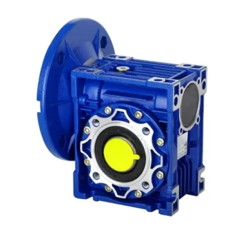
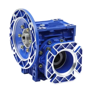
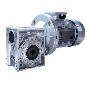
Product Description
Product Parameters
Editing and broadcasting of main materials
1. Body, die-casting aluminum alloy;
2. Worm shaft, 20 Crq steel, high temperature treatment;
3. Worm gear, nickel bronze alloy;
4. Aluminum alloy body, sandblasting and surface anti-corrosion treatment;
5. Cast iron body, painted with bIu RA5571.
Regular center distance specification editing and broadcasting
Center distance: 130 (unit: mm).
Output hole/shaft diameter: 11, 14, 18, 25, 28, 35, 42, 45 (unit: mm)
Detailed Photos
|
NMRV-063-30-VS–AS-80B5-0.75KW-B3 |
|||
|
NMRV |
Means hole-input with flange |
||
|
NRV |
Means shaft-input without flange |
||
|
063 |
Centre-to-centre spacing of worm-gear speed reducer |
||
|
30 |
ratio |
||
|
VS |
Double input shaft |
F1(FA) |
Flange putput shaft |
|
AS |
Single output shaft |
AB |
Double output shaft |
|
PAM |
|
80B5 |
Motor mounting facility |
|
0.75KW |
|
B3 |
Mounting position |
|
N2 |
NRV571 |
NRV030 |
NRV040 |
NRV050 |
NRV063 |
NRV075 |
NRV090 |
NRV110 |
NRV130 |
|
400 |
390 |
530 |
1571 |
1400 |
1830 |
2160 |
2390 |
3571 |
3950 |
|
250 |
460 |
620 |
1200 |
1650 |
2150 |
2520 |
2800 |
3530 |
4610 |
|
150 |
550 |
740 |
1420 |
1960 |
2450 |
2990 |
3310 |
4180 |
5470 |
|
100 |
630 |
850 |
1620 |
2250 |
2910 |
3430 |
3800 |
4790 |
6260 |
|
60 |
740 |
1000 |
1920 |
2660 |
3450 |
4060 |
4500 |
5680 |
7420 |
|
40 |
850 |
1150 |
2200 |
3050 |
3950 |
4650 |
5150 |
6500 |
8500 |
|
25 |
990 |
1350 |
2570 |
3570 |
4620 |
5440 |
6571 |
7600 |
9940 |
|
10 |
1350 |
1830 |
3490 |
4840 |
6270 |
7380 |
8180 |
10320 |
13500 |
|
|
|
|
|
|
|
|
|
|
|
|
A |
50 |
65 |
84 |
101 |
120 |
131 |
162 |
191 |
203 |
|
B |
38 |
50 |
64 |
76 |
95 |
101 |
122 |
151 |
163 |
Use and safety guarantee
1. Please check and confirm the matching intensity between worm gear reducer and mechanical equipment before use to assure that it is in the safety range of worm gear reducer performance parameters
2. Worm gear reducer has filled with WA460 lubricating oil. Please replace the lubricating oil after the first starting of 400 hours and after then 4000 hours for lubricating oil replacing cycle
3. There should be enough lubrication in worm gear box and keep regular check with the oil level.
4. When installation. please be careful to avoid sharp instruments bruising the oil seals on output shaft to cause leakage
5. Please confirm the rotation direction before mechanical connection. If the rotation direction is not correct, it will possible injury or damage the devices
6. Please set safety covers in rotating position to avoid of injuring
7. Please pay full attention: it is very dangerous if there is off or falling when movin
| Hardness: | Hardened Tooth Surface |
|---|---|
| Installation: | 90 Degree |
| Layout: | Expansion |
| Gear Shape: | Bevel Gear |
| Step: | Single-Step |
| Type: | Gear Reducer |
| Samples: |
US$ 30/Piece
1 Piece(Min.Order) | |
|---|

How to Install and Align a Worm Reducer Properly
Proper installation and alignment of a worm reducer are crucial for ensuring optimal performance and longevity. Follow these steps to install and align a worm reducer:
- Preparation: Gather all the necessary tools, equipment, and safety gear before starting the installation process.
- Positioning: Place the worm reducer in the desired location, ensuring that it is securely mounted to a stable surface. Use appropriate fasteners and mounting brackets as needed.
- Shaft Alignment: Check the alignment of the input and output shafts. Use precision measurement tools to ensure that the shafts are parallel and in line with each other.
- Base Plate Alignment: Align the base plate of the reducer with the foundation or mounting surface. Ensure that the base plate is level and properly aligned before securing it in place.
- Bolt Tightening: Gradually and evenly tighten the mounting bolts to the manufacturer’s specifications. This helps ensure proper contact between the reducer and the mounting surface.
- Check for Clearance: Verify that there is enough clearance for any rotating components or parts that may move during operation. Avoid any interference that could cause damage or performance issues.
- Lubrication: Apply the recommended lubricant to the worm reducer according to the manufacturer’s guidelines. Proper lubrication is essential for smooth operation and reducing friction.
- Alignment Testing: After installation, run the worm reducer briefly without a load to check for any unusual noises, vibrations, or misalignment issues.
- Load Testing: Gradually introduce the intended load to the worm reducer and monitor its performance. Ensure that the reducer operates smoothly and efficiently under the load conditions.
It’s important to refer to the manufacturer’s installation guidelines and specifications for your specific worm reducer model. Proper installation and alignment will contribute to the gearbox’s reliability, efficiency, and overall functionality.

How to Calculate the Input and Output Speeds of a Worm Gearbox?
Calculating the input and output speeds of a worm gearbox involves understanding the gear ratio and the principles of gear reduction. Here’s how you can calculate these speeds:
- Input Speed: The input speed (N1) is the speed of the driving gear, which is the worm gear in this case. It is usually provided by the manufacturer or can be measured directly.
- Output Speed: The output speed (N2) is the speed of the driven gear, which is the worm wheel. To calculate the output speed, use the formula:
N2 = N1 / (Z1 * i)
Where:
N2 = Output speed (rpm)
N1 = Input speed (rpm)
Z1 = Number of teeth on the worm gear
i = Gear ratio (ratio of the number of teeth on the worm gear to the number of threads on the worm)
It’s important to note that worm gearboxes are designed for gear reduction, which means that the output speed is lower than the input speed. Additionally, the efficiency of the gearbox, friction, and other factors can affect the actual output speed. Calculating the input and output speeds is crucial for understanding the performance and capabilities of the worm gearbox in a specific application.

Preventing Backlash in a Worm Gearbox
Backlash in a worm gearbox can lead to reduced accuracy, positioning errors, and decreased overall efficiency. Here are steps to prevent or minimize backlash:
- High-Quality Components: Use high-quality worm gears and worm wheels with tight manufacturing tolerances. Precision components will help reduce backlash.
- Proper Meshing: Ensure the worm gear and worm wheel are properly aligned and meshed. Improper meshing can lead to increased backlash.
- Preload: Applying a small amount of preload to the worm gear can help reduce backlash. However, excessive preload can increase friction and wear.
- Anti-Backlash Mechanisms: Consider using anti-backlash mechanisms, such as spring-loaded systems or adjustable shims, to compensate for any inherent backlash.
- Lubrication: Proper lubrication can reduce friction and play a role in minimizing backlash. Use a lubricant that provides good film strength and reduces wear.
- Maintenance: Regularly inspect and maintain the gearbox to identify and address any changes in backlash over time.
It’s important to strike a balance between reducing backlash and maintaining smooth operation. Consulting with gearbox experts and following manufacturer guidelines will help you optimize your worm gearbox’s performance while minimizing backlash.


editor by CX 2023-09-12