Product Description
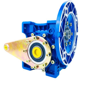
SHTDN High Speed Gearbox for Twin Screw Extruder Machine
SHTDN Twin Screw Extruder Gearbox Introduction
Twin Screw Gearbox adopting latest standard ISO1328,the precision of cylindrical gear of spherical involute, and combining our long term experience and specialty of twin screw extruder, SHTDN gearboxes are meticulously designed with top advanced designing ideas in the world for co-orientated rotating twin screw extruder, with entirely independent Intellectual Property Rights.
The gears are made of carburizing steel of high-strength alloy of good quality by carburizing and quenching for teeth, of which all the gear grinding processes are finished by imported gear grinding machines. Gear parameters are optimized and specially designed for the characteristics of twin screw extruder, reducing stress concentration on root of gear and improving gear surface conditions. We have improved gear intension of flexural fatigue, fatigue strength and ratio of wide diameter. We have also adopted the latest designing idea and technology of heating treatment for the structure of gears, thereby ensured gears from uniformity of precision and strength.
Features:
— High Speed
—Triaxiality parallel design improve B axis bearing capacity.
—Simple manufacture and convenient assemply.Lower the cost.
—Modular structure design achieve 2 kinds of gearbox torque grade.
SHTDN Twin Screw Extruder Gearbox Parameters
|
SHTDN Gearbox Power&Torque Table
|
|
Model
|
CD(MM)
|
Torque Grade(T/A3)
|
RPM 300r/min
|
RPM 400r/min
|
RPM 500r/min
|
|
SHTD20N
|
18
|
<13
|
—
|
—
|
—
|
|
SHTD25N
|
22
|
<13
|
—
|
—
|
11kw
|
|
SHTD30N
|
26
|
<13
|
—
|
—
|
—
|
|
SHTD35N
|
30
|
<13
|
18.5kw
|
22kw
|
30kw
|
|
SHTD40N
|
34.5
|
<13
|
30kw
|
45kw
|
55kw
|
|
SHTD50N
|
42
|
<13
|
55kw
|
75kw
|
90kw
|
|
SHTD52N
|
43
|
<13
|
55kw
|
75kw
|
90kw
|
|
SHTD58N
|
48
|
<13
|
90kw
|
110kw
|
132kw
|
|
SHTD65N
|
52
|
<13
|
110kw
|
132kw
|
160kw
|
|
SHTD75N
|
60
|
<13
|
160kw
|
220kw
|
250kw
|
|
SHTD85N
|
67.8
|
<13
|
220kw
|
315kw
|
400kw
|
|
SHTD95N
|
78
|
<13
|
350kw
|
450kw
|
550kw
|
Production Process
Packing&Delivery
Packing Details: According to your order quantity packaging,shipping wooden boxes,air carton.
Delivery Details: 5-60days after order.
|
1.Rust-proof oil processing,
Prevent rust in transit.
|
2.Oiled paper packages,
Prevent oil dry.
|
3.Bubble wrap package,
Prevent collosions.
|
| 4.Special foam packaging. |
5.Packing |
6.Sealing |
Our Service
|
24-hour Hotline
No matter when and where
to call we can find our service to you.
|
Pre-sales Consultation
We have 5 sales people online,
and whether you have any question
can be solved through online
communication,welcome your consultation.
|
After-sales Services
Receive products have any
questions about the product,
can look for us,we will help
you deal with the the first time,to your satisfaction.
|
|
All ZT keep pay attention to every step of the details,We are looking CHINAMFG to the forge ahead together with you!
|
FAQ
How long does it take to get my products since I paid for them?
—According to your order quantity,we will give you a reasonable delivery date.
Can I get the warranty of 1 year for free?
—If you need the warranty,you should pay for it.If not,do not worry ,we have confidence in our products.
How is your after-sale service?
—You will get our help in time as long as you find something wrong about our produces.Believe us,you deserve the best.
What machine does the product apply to?
—Twin Screw Extruder Machine.
| Application: |
Machinery |
| Function: |
Speed Reduction |
| Layout: |
Double Drive Gearbox |
| Hardness: |
Hardened Tooth Surface |
| Installation: |
Horizontal Type |
| Step: |
Three-Step |
| Customization: |
Available
|
Customized Request
|

Self-Locking Properties in a Worm Gearbox
Yes, worm gearboxes exhibit self-locking properties, which can be advantageous in certain applications. Self-locking refers to the ability of a mechanism to prevent the transmission of motion from the output shaft back to the input shaft when the system is at rest. Worm gearboxes inherently possess self-locking properties due to the unique design of the worm gear and worm wheel.
The self-locking behavior arises from the angle of the helix on the worm shaft. In a properly designed worm gearbox, the helix angle of the worm is such that it creates a mechanical advantage that resists reverse motion. When the gearbox is not actively driven, the friction between the worm threads and the worm wheel teeth creates a locking effect.
This self-locking feature makes worm gearboxes particularly useful in applications where holding a load in position without external power is necessary. For instance, they are commonly used in situations where there’s a need to prevent a mechanism from backdriving, such as in conveyor systems, hoists, and jacks.
However, it’s important to note that while self-locking properties can be beneficial, they also introduce some challenges. The high friction between the worm gear and worm wheel during self-locking can lead to higher wear and heat generation. Additionally, the self-locking effect can reduce the efficiency of the gearbox when it’s actively transmitting motion.
When considering the use of a worm gearbox for a specific application, it’s crucial to carefully analyze the balance between self-locking capabilities and other performance factors to ensure optimal operation.

How to Calculate the Efficiency of a Worm Gearbox
Calculating the efficiency of a worm gearbox involves determining the ratio of output power to input power. Efficiency is a measure of how well the gearbox converts input power into useful output power without losses. Here’s how to calculate it:
- Step 1: Measure Input Power: Measure the input power (Pin) using a power meter or other suitable measuring equipment.
- Step 2: Measure Output Power: Measure the output power (Pout) that the gearbox is delivering to the load.
- Step 3: Calculate Efficiency: Calculate the efficiency (η) using the formula: Efficiency (η) = (Output Power / Input Power) * 100%
For example, if the input power is 1000 watts and the output power is 850 watts, the efficiency would be (850 / 1000) * 100% = 85%.
It’s important to note that efficiencies can vary based on factors such as gear design, lubrication, wear, and load conditions. The calculated efficiency provides insight into how effectively the gearbox is converting power, but it’s always a good practice to refer to manufacturer specifications for gearbox efficiency ratings.

What is a Worm Gearbox and How Does It Work?
A worm gearbox, also known as a worm gear reducer, is a mechanical device used to transmit rotational motion and torque between non-parallel shafts. It consists of a worm screw and a worm wheel, both of which have helical teeth. The worm screw resembles a threaded cylinder, while the worm wheel is a gear with teeth that mesh with the worm screw.
The working principle of a worm gearbox involves the interaction between the worm screw and the worm wheel. When the worm screw is rotated, its helical teeth engage with the teeth of the worm wheel. As the worm screw rotates, it translates the rotational motion into a perpendicular motion, causing the worm wheel to rotate. This perpendicular motion allows the worm gearbox to achieve a high gear reduction ratio, making it suitable for applications that require significant speed reduction.
One of the key features of a worm gearbox is its ability to provide a high gear reduction ratio in a compact design. However, due to the sliding nature of the meshing teeth, worm gearboxes may exhibit higher friction and lower efficiency compared to other types of gearboxes. Therefore, they are often used in applications where efficiency is not the primary concern but where high torque and speed reduction are essential, such as conveyor systems, elevators, automotive steering systems, and certain industrial machinery.


editor by CX 2023-10-25
Sure, a equipment can be referred to as a cog or a sprocket dependent on the context and the unique application in which it is employed. Although the phrases equipment, cog, and sprocket are typically made use of interchangeably, there can be slight discrepancies in their utilization:
one. Gear: The expression “equipment” is a standard time period made use of to explain any toothed mechanical ingredient that meshes with yet another equipment to transmit electrical power. Gears can have numerous tooth profiles (these types of as involute, cycloidal, or straight-sided) and can be used in a wide assortment of apps, which include equipment, automotive transmissions, and industrial programs.
2. Cog: The expression “cog” is generally applied to refer to a gear in the context of scaled-down or individual gears. It is frequently associated with gears utilised in clockwork mechanisms or smaller mechanical systems. Cog is from time to time employed to explain a equipment with a easy tooth profile, ordinarily flat or straight-sided.
three. China sprocket distributor: The phrase “sprocket” particularly refers to a equipment that is utilized in conjunction with a chain in a chain push technique. Sprockets have teeth that are designed to have interaction with the inbound links of a chain, China sprocket distributor generating a constructive push mechanism. Sprockets are normally discovered in apps these as bicycles, motorcycles, and industrial machinery that employ chain drives.
In summary, although the phrases equipment, cog, and sprocket can be made use of interchangeably in numerous situations, “gear” is a typical expression, “cog” often refers to more compact or particular person gears, and “sprocket” particularly denotes a equipment utilized in conjunction with a chain in a chain generate system.
Yes, a equipment can be referred to as a cog or a sprocket dependent on the context and the specific software in which it is utilized. Even though the terms equipment, cog, and sprocket are often applied interchangeably, China sprocket there can be slight discrepancies in their utilization:
1. Equipment: The expression “equipment” is a normal expression utilised to explain any toothed mechanical ingredient that meshes with a different equipment to transmit power. Gears can have various tooth profiles (this kind of as involute, cycloidal, or straight-sided) and can be made use of in a wide range of apps, such as equipment, automotive transmissions, and industrial devices.
two. Cog: The expression “cog” is generally used to refer to a gear in the context of smaller or person gears. It is usually related with gears utilised in clockwork mechanisms or smaller mechanical methods. Cog is often used to describe a equipment with a straightforward tooth profile, typically flat or straight-sided.
three. Sprocket: The term “China sprocket” exclusively refers to a equipment that is utilised in conjunction with a chain in a chain drive method. Sprockets have tooth that are created to interact with the back links of a chain, producing a good push system. Sprockets are usually identified in purposes these kinds of as bicycles, bikes, and industrial machinery that benefit from chain drives.
In summary, even though the phrases equipment, cog, and sprocket can be employed interchangeably in numerous scenarios, “gear” is a basic expression, “cog” frequently refers to scaled-down or particular person gears, and “sprocket” precisely denotes a gear made use of in conjunction with a chain in a chain drive program.
A China spline shaft shaft is a type of mechanical element designed to transmit torque and rotational movement concerning two or far more mechanical devices. It is composed of a cylindrical shaft with a sequence of ridges or enamel, known as splines, machined alongside its length. The splines on the shaft correspond to matching grooves or slots on a mating part, these as a equipment, coupling, or sleeve.
The purpose of a spline shaft is to supply a protected and precise connection involving two rotating factors whilst making it possible for relative motion among them. The mating ingredient, China spline shaft normally referred to as a spline hub or sleeve, suits on to the spline shaft, and the splines interlock to transfer torque and rotational forces.
Spline shafts give several pros in mechanical programs:
one. Torque Transmission: Spline shafts effectively transmit torque from a single element to a different, enabling electric power transfer and rotational motion.
2. Exact Positioning: The interlocking splines present accurate and repeatable positioning among the shaft and the mating ingredient, making sure precise alignment and protecting against slippage or misalignment.
3. Load Distribution: The splines distribute the load throughout a larger floor area, decreasing stress concentration on unique tooth and enhancing the all round load-carrying capacity of the shaft.
four. Compensation for Misalignment: Spline shafts can accommodate slight misalignments amongst elements thanks to production tolerances, thermal enlargement, or other aspects, permitting for easy operation and decreased put on.
5. Simple Assembly and Disassembly: Spline shafts facilitate easy assembly and disassembly of the connected elements, China spline shaft supplier making maintenance, repairs, and component substitution easier.
Spline shafts find purposes in several industries and equipment, including automotive transmissions, electricity resources, industrial machinery, aerospace devices, and robotics. The specific structure and dimensions of the spline shaft can change primarily based on aspects these as the torque demands, the quantity and kind of splines, the shaft diameter, and the meant software.
It’s value noting that spline shafts can have various spline varieties, this kind of as involute splines, straight-sided splines, or serrated splines, each with its own geometric traits and certain programs.
In the context of a semi-truck, a torque arm is a part of the rear suspension method that aids command China torque arm and deal with the torque produced by the drivetrain. It is typically found in trucks with a reliable rear axle configuration.
The primary intent of a torque arm on a semi-truck is to resist the rotational forces, or torque, generated by the motor and drivetrain, significantly for the duration of acceleration, braking, and load transfer. It aids maintain security, prevent axle wrap or wheel hop, and distribute the torque evenly to the rear wheels.
 Listed here are some critical factors about the torque arm in a semi-truck:
one. Place and Mounting: The torque arm is generally positioned among the rear axle housing and the truck’s frame or chassis. It is attached at just one conclude to the rear axle and at the other close to the frame or chassis utilizing brackets or bushings.
two. Control of Axle Actions: As torque is transmitted from the drivetrain to the rear axle, the torque arm resists the upward and forward rotational forces that can cause axle wrap. Axle wrap refers to the twisting or rotation of the rear axle, which can negatively effect traction, security, and the in general functionality of the truck.
3. Balance and Traction: By restricting axle wrap, the torque arm allows sustain steadiness and traction. It guarantees that power is efficiently transferred to the rear wheels, lessening wheel hop and too much axle movement that could guide to decline of traction or command.
4. Load Distribution: The torque arm also assists in distributing the fat and torque load involving the rear wheels. By correctly controlling the torque transfer, it will help guarantee even tire dress in, lowers strain on drivetrain components, and encourages far better managing attributes.
five. Variations and Structure: The design and configuration of torque arms can change dependent on the unique truck design and manufacturer. Some vans might have a one China torque arm supplier arm, when others might employ a dual torque arm set up for China torque arm supplier increased security and command.
In general, the torque arm in a semi-truck performs a essential purpose in managing the torque produced by the drivetrain and rear axle. It will help retain stability, protect against axle wrap, distribute torque, and optimize traction, contributing to the secure and successful procedure of the truck.
.webp) 6. Temperature Resistance: Aluminum has great heat dissipation attributes, China aluminum furniture supplier which signifies it can quickly release heat and continue to be awesome to the touch. This can be valuable in incredibly hot climates or when uncovered to immediate sunlight, as it decreases the chance of the furniture starting to be uncomfortably incredibly hot.
6. Temperature Resistance: Aluminum has great heat dissipation attributes, China aluminum furniture supplier which signifies it can quickly release heat and continue to be awesome to the touch. This can be valuable in incredibly hot climates or when uncovered to immediate sunlight, as it decreases the chance of the furniture starting to be uncomfortably incredibly hot. A torque limiting extension bar, also recognised as a torque adhere, is a device that is applied to protect towards overtightening of fasteners. It is effective by flexing when a guaranteed sum of torque is utilized, which allows reduce the fastener from getting to be tightened any more.


 four. Best Spline Profile: The layout of the spline profile can influence tension focus.