Product Description
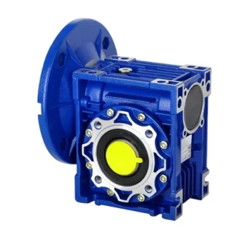
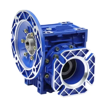
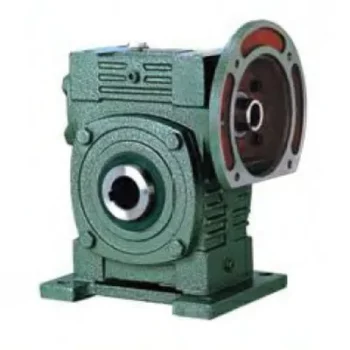
SC Transmission Customized small gear motor nmrv 063
gearbox 220v dc motor with reducer for elevator
Product Description
NMRV NRV SERIES WORM GEAR SPEED REDUCER FEATURES:
The weight of the NMRV reducer is relatively light. The shell is made of aluminium alloy. It has the advantages of light weight, superior strength, exquisite appearance, high heat dissipation performance, long service life, no noise and so on. It is easy to connect with the motor.
NMRV reducer is a more practical transmission equipment, and in the appearance design and its integration are more in line with the needs of the public than other types of reducers.
The application field and popularity of the RV reducer made of aluminium alloy are even better than other types of reducer. It is a kind of reducer with high practicability, and also a combination of advanced technology at home and abroad.
NMRV reducer is very convenient to connect with ordinary motor, CVT, flange electromagnetic clutch brake unit, and does not need coupling. Suitable for all-round installation, and the output torque is relatively large, work fairly smoothly and so on.
-
Product Parameters
- RV – Sizes:–150
- Input Options: with input shaft, With Square flange,With Input Flange
- Input Power 0.06 to 11 kW
- RV-Size from 030 to 105 in die-cast aluminium alloy budy and over 110 in cast iron
- Ratios between 5 and 100
- Max torque 1550 N.m and admissible output radial loads max 8771 N
- Aluminium units are supplied complete with synthetic oil and allow for universal mounting positions, with no need to modify lubricant quantity
- Worm wheel: Copper (9-4/10-1/12-2 for options).
- Loading capacity in accordance with: ISO 9001:2015/GB/T 19001-2016
- Worm gear reducers are available with diffferent combinations: NMRV+NMRV, NMRVpower+NMRV, JWB+NMRV
- NMRV, NRV+VS,NMRV+AS,NMRV+VS,NMRV+F
- Options: torque arm, output flange, viton oil seals, low/high temperature oil, filling/drain/breather/level plug.
Detailed Photos
Company Profile
FAQ
Shipping
/* January 22, 2571 19:08:37 */!function(){function s(e,r){var a,o={};try{e&&e.split(“,”).forEach(function(e,t){e&&(a=e.match(/(.*?):(.*)$/))&&1
| Application: | Motor, Machinery, Agricultural Machinery |
|---|---|
| Gear Shape: | Bevel Gear |
| Type: | Worm Reducer |
| Output Torque: | 2.6n.M-1195n.M |
| Input: | Flange or Shaft |
| Input Power: | 0.1-25.8kw |
| Samples: |
US$ 50/Piece
1 Piece(Min.Order) | |
|---|
| Customization: |
Available
| Customized Request |
|---|

How to Install and Align a Worm Reducer Properly
Proper installation and alignment of a worm reducer are crucial for ensuring optimal performance and longevity. Follow these steps to install and align a worm reducer:
- Preparation: Gather all the necessary tools, equipment, and safety gear before starting the installation process.
- Positioning: Place the worm reducer in the desired location, ensuring that it is securely mounted to a stable surface. Use appropriate fasteners and mounting brackets as needed.
- Shaft Alignment: Check the alignment of the input and output shafts. Use precision measurement tools to ensure that the shafts are parallel and in line with each other.
- Base Plate Alignment: Align the base plate of the reducer with the foundation or mounting surface. Ensure that the base plate is level and properly aligned before securing it in place.
- Bolt Tightening: Gradually and evenly tighten the mounting bolts to the manufacturer’s specifications. This helps ensure proper contact between the reducer and the mounting surface.
- Check for Clearance: Verify that there is enough clearance for any rotating components or parts that may move during operation. Avoid any interference that could cause damage or performance issues.
- Lubrication: Apply the recommended lubricant to the worm reducer according to the manufacturer’s guidelines. Proper lubrication is essential for smooth operation and reducing friction.
- Alignment Testing: After installation, run the worm reducer briefly without a load to check for any unusual noises, vibrations, or misalignment issues.
- Load Testing: Gradually introduce the intended load to the worm reducer and monitor its performance. Ensure that the reducer operates smoothly and efficiently under the load conditions.
It’s important to refer to the manufacturer’s installation guidelines and specifications for your specific worm reducer model. Proper installation and alignment will contribute to the gearbox’s reliability, efficiency, and overall functionality.

How to Calculate the Input and Output Speeds of a Worm Gearbox?
Calculating the input and output speeds of a worm gearbox involves understanding the gear ratio and the principles of gear reduction. Here’s how you can calculate these speeds:
- Input Speed: The input speed (N1) is the speed of the driving gear, which is the worm gear in this case. It is usually provided by the manufacturer or can be measured directly.
- Output Speed: The output speed (N2) is the speed of the driven gear, which is the worm wheel. To calculate the output speed, use the formula:
N2 = N1 / (Z1 * i)
Where:
N2 = Output speed (rpm)
N1 = Input speed (rpm)
Z1 = Number of teeth on the worm gear
i = Gear ratio (ratio of the number of teeth on the worm gear to the number of threads on the worm)
It’s important to note that worm gearboxes are designed for gear reduction, which means that the output speed is lower than the input speed. Additionally, the efficiency of the gearbox, friction, and other factors can affect the actual output speed. Calculating the input and output speeds is crucial for understanding the performance and capabilities of the worm gearbox in a specific application.

Types of Worm Gear Configurations and Their Uses
Worm gear configurations vary based on the arrangement of the worm and the gear it engages with. Here are common types and their applications:
- Single Enveloping Worm Gear: This configuration offers high torque transmission and efficiency. It’s used in heavy-duty applications like mining equipment and industrial machinery.
- Double Enveloping Worm Gear: With increased contact area, this type provides higher load capacity and improved efficiency. It’s used in aerospace applications, robotics, and precision machinery.
- Non-Throated Worm Gear: This type has a cylindrical worm without a throat. It’s suitable for applications requiring precise motion control, such as CNC machines and robotics.
- Throated Worm Gear: Featuring a throat in the worm, this configuration offers smooth engagement and higher load capacity. It’s used in conveyors, elevators, and automotive applications.
- Non-Modular Worm Gear: In this design, the worm and gear are a matched set, resulting in better meshing and efficiency. It’s utilized in various industries where customization is essential.
- Modular Worm Gear: This type allows interchangeability of worm and gear components, providing flexibility in design and maintenance. It’s commonly used in conveyors, mixers, and material handling systems.
Selecting the appropriate worm gear configuration depends on factors such as load capacity, efficiency, precision, and application requirements. Consulting gearbox experts can help determine the best configuration for your specific needs.


editor by CX 2024-03-27
China Professional 30mm Small High Torque Planetary Electric Gearbox for DC Motor with Free Design Custom
Item Description
30mm Planetary Gearbox
Mechanical Proportions:
Gearbox Description:
| Housing content |
Bearing at output |
Radial load (10mm from the flange) |
Shaft axial load |
Shaft press fit force, max. |
Radial play of shaft |
Thrust play of shaft |
Backlash at no-load |
| Steel | Sleeve bearings | ≤3Kgf | ≤2.5Kgf | ≤10Kgf | ≤0.08mm | ≤0.2mm | ≤3° |
| Metal | Ball bearings | ≤3.5Kgf | ≤2.5Kgf | ≤10Kgf | ≤0.05mm | ≤0.2mm | ≤3° |
Motor Shaft Pinion Specification:
| Module | No. of teeth | Pressure angle | Hole diameter | Reduction ratio. |
| .five | 11 | 20° | two.28,2.48,2.ninety eight | 1/5,1/19,1/27,1/seventy one,1/a hundred,1/139,1/264,1/516,1/721 |
| .5 | 17 | 20° | two.28,2.48,2.98 | one/4,1/14,1/fifty one,1/189 |
| .five | eight | 20° | two.28 | 1/35,1/939 |
Gearbox Specification:
| Reduction ratio | one/four | one/five | 1/fourteen | one/19 | one/27 | one/35 | one/fifty one | 1/71 | one/a hundred | 1/139 | one/189 | one/264 | one/516 | 1/721 | 1/939 |
| Rated tolerance torque |
two | two | three | three | 4 | four | six | 6 | 8 | eight | 10 | 10 | 10 | 10 | ten |
| Max momentary tolerance torque |
six | 6 | 9 | nine | 12 | twelve | 18 | eighteen | 24 | 24 | thirty | thirty | thirty | 30 | 30 |
| Performance | eighty% | 80% | 70% | 70% | 70% | 70% | 60% | 60% | sixty% | 60% | fifty% | 50% | fifty% | 50% | fifty% |
| Duration (L-mm) |
23.6 | 23.six | thirty | thirty | thirty | 30 | 36.4 | 36.four | 36.4 | 36.four | 42.8 | forty two.8 | 42.8 | forty two.8 | 42.8 |
| Bodyweight (g) |
79 | 79 | ninety two | 92 | 92 | 92 | 107 | 107 | 107 | 107 | 122 | 122 | 122 | 122 | 122 |
About Us:
We specialised in researching, building and servicing electrical motors, gearbox and large precision gears with the little modules.
Soon after a long time of improvement, we have an impartial solution layout and the R&D team, service group, and skilled good quality management group.
What is far more, we have 2 joint ventures. One is situated in HangZhou, which produces hybrid stepper motor, precious linear stepper motor, brushless DC motor, servo motor, stepper motor driver, brushless motor driver, encoder and brake.
Yet another 1 is located in HangZhou, which generates DC gear motor. The factory has dozens of CNC equipment and high precision examination products, implements the procedure administration and automated procedure in most making approach.
We also have 2 cooperation factories. A single is generating AC reversible synchronous motor and AC servo motor, the other 1 is generating linear long lasting stepper motor, long lasting stepper motors.
Customer’s Going to:
Connected Merchandise:
These compact, lightweight, lower backlash inline gear reducers were initially designed for encoder purposes. They are also appropriate for numerous other drive methods. Encoder equipment reducers have a very low moment of inertia at the shaft enter and are rated for input speeds up to 3000 rpm. Two body dimensions are offered with gear ratios from 4.ninety six:1 to 3600:1. Our encoder gearbox sync pads are accessible from inventory.
Equipment reducers, also referred to as reducers, come in numerous transmission designs and are created to multiply torque and reduce input velocity to a preferred output velocity. The main benefit of inline gearboxes is their capacity to sustain handle in apps involving high rotational speeds. Their performance and ability to offer high enter speeds with minimum backlash make inline reducer gearboxes best for a wide range of movement handle purposes
